1.3.1.1. Livox LiDAR Communication Protocol–Avia2
Release History |
||
|---|---|---|
Date |
Version |
Description |
20260730 |
v1.0 |
1. Initialized version |
1.3.1.2. Overview
This communication protocol is only used for livox Avia2 LiDAR.
1.3.1.2.1. Protocol Types
There are two types of data protocols between the user and the LiDAR, see as below:
Point cloud data protocol:
Point cloud data sampled and output by the LiDAR;
Internal IMU data of the LiDAR.
For details, see (Data Types).
Control command protocol:
Configure and query LiDAR parameters; LiDAR reset;
Push and query LiDAR status;
Upgrade related;
For details, see (CMD Details).
Both protocols are encapsulated using UDP data segments, and the protocol data is Little-endian.
1.3.1.2.2. LiDAR Working Status
The state machine of the current LiDAR is shown in the figure. The state enumeration values currently used by the LiDAR product are as follows:
LiDAR Status |
Enumeration Value |
Whether to Support User Settings |
|---|---|---|
SAMPLING |
0x01 |
Support(By Parameter Configuration) |
IDLE |
0x02 |
Support(By Parameter Configuration) |
ERROR |
0x04 |
Not Support |
SELFCHECK |
0x05 |
Not Support |
MOTORSTARUP |
0x06 |
Not Support |
READY |
0x09 |
Support(By Parameter Configuration) |

1.3.1.2.3. Port Description
The source port and destination port are explained as follows according to the different data types:
Data Type |
Transmission Direction |
LiDAR Port |
Host Computer Port |
Transmission Type |
Transmission Protocol |
|---|---|---|---|---|---|
Device Type Query |
LiDAR <—-> PC |
56000 |
Any |
Broadcast |
UDP |
56000 is used as the fixed listening port of Livox LiDAR, mainly used for the host computer to query the device through broadcast:
1. Only the device type query command (cmd_id: 0x0000) is supported. The host computer obtains the specific device type of the LiDAR through this port. This command response is replied by broadcast, so that when the host computer and the LiDAR IP are not in the same network segment, the host computer can still identify the LiDAR.
Avia2 Communication Port:
Data Type |
Transmission Direction |
LiDAR Port |
Host Computer Port |
Transmission Type |
Transmission Protocol |
|---|---|---|---|---|---|
Control Command |
LiDAR<—> Host Computer |
56100 |
Any (56101 recommended) |
Unicast |
UDP |
Push Command |
LiDAR —> Host Computer |
56200 |
Configurable (default 56201) |
Default Unicast |
UDP |
Point Cloud Data |
LiDAR —> Host Computer |
56300 |
Configurable (default 56301) |
Default Unicast(Support Multicast) |
UDP |
IMU Data |
LiDAR —> Host Computer |
56400 |
Configurable (default 56401) |
Default Unicast(Support Multicast) |
UDP |
LOG Data |
LiDAR <—> Host Computer |
56500 |
Any (56501 recommended) |
Unicast |
UDP |
1.3.1.3. Point Cloud & IMU Data Protocol
1.3.1.3.1. Protocol Format
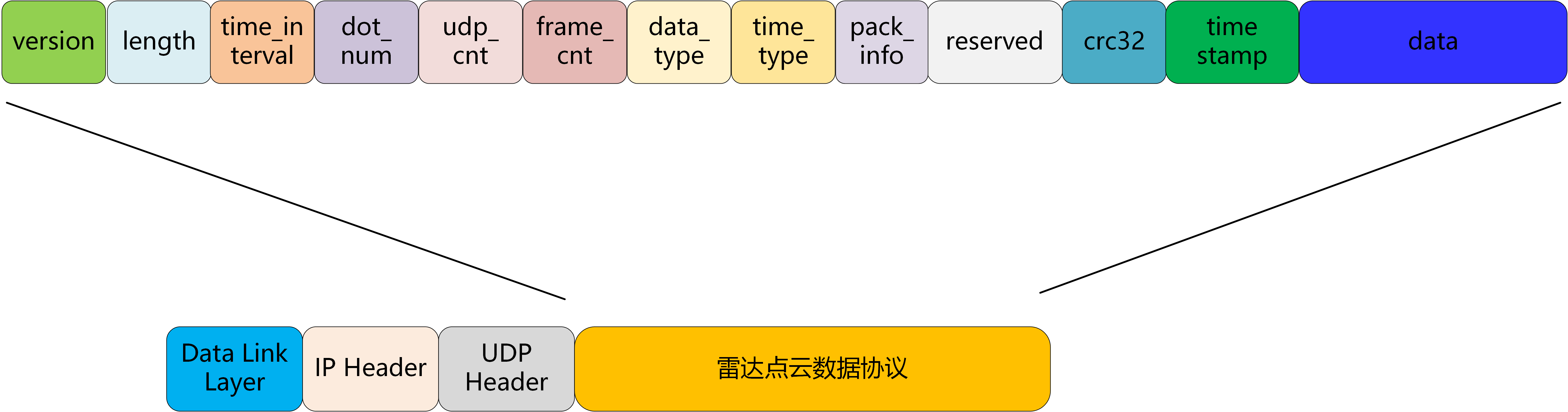
Point cloud data format output by the LiDAR:
Field |
Offset (bytes) |
Size (bytes) |
Description |
|---|---|---|---|
version |
0 |
1 |
Package protocol version: currently 1 |
length |
1 |
2 |
The length of the entire UDP data segment starting from |
reserved |
3 |
2 |
Reserved |
dot_num |
5 |
2 |
The current UDP packet data field contains the number of points |
udp_cnt |
7 |
2 |
Point cloud UDP packet count, each UDP packet is incremented by 1 in turn, and cleared to 0 at the beginning of the point cloud frame |
frame_cnt |
9 |
1 |
This field is not yet enabled |
data_type |
10 |
1 |
Data type. For details, see (Data Types) |
time_type |
11 |
1 |
Timestamp type. For details, see (Timestamp) |
reserved1 |
12 |
12 |
Reserved |
crc32 |
24 |
4 |
timestamp+data segment check code, using CRC-32 algorithm (see (CRC Algorithm) for details) |
timestamp |
28 |
8 |
Point cloud timestamp. For details, see (Timestamp) |
data |
36 |
– |
Data information. For details, see (Data Types) |
1.3.1.3.2. Timestamp
Points within every 100ms form a frame; data packets within this 100ms share the same timestamp.
Timestamp type:
Timestamp Type |
Sync Source Type |
Data Format |
Description |
|---|---|---|---|
0 |
No synchronization source, the timestamp is the time when the LiDAR is turned on |
uint64_t |
Unit: ns |
1 |
gPTP/PTP synchronization, the time of master clock source as a timestamp |
uint64_t |
Unit: ns |
2 |
GPS time synchronization |
uint64_t |
Unit: ns |
5 |
NTP time synchronization |
uint64_t |
Unit: ns |
Notice:
The time limit for GPS time synchronization is from 1/1/2000 to 31/12/2037
PTP time synchronization does not support IEEE1588v2.1
Not recommended for use in scenarios where IEEE1588v2.0 and gPTP coexist;
1.3.1.3.3. Data Types
There are N samples in each packet. The size of N depends on the data type.
There are 3 data types, the default point cloud data type is 1:
Data Type |
Sampling Type |
Echo Mode |
Coordinate Mode |
|---|---|---|---|
0 |
IMU data |
||
1 |
Point cloud data |
Single echo mode |
Cartesian coordinates |
17 |
Point cloud data |
Dual echo mode |
Cartesian coordinates |
Data Type 0
IMU Data:
Field |
Offset (bytes) |
Data Type |
Description |
|---|---|---|---|
gyro_x |
0 |
float |
Unit: rad/s |
gyro_y |
4 |
float |
Unit: rad/s |
gyro_z |
8 |
float |
Unit: rad/s |
acc_x |
12 |
float |
Unit: g |
acc_y |
16 |
float |
Unit: g |
acc_z |
20 |
float |
Unit: g |
Data Type 1
Single echo Cartesian coordinate data format:
Field |
Offset (bytes) |
Data Type |
Description |
|---|---|---|---|
x |
0 |
int32_t |
X axis, Unit: mm |
y |
4 |
int32_t |
Y axis, Unit: mm |
z |
8 |
int32_t |
Z axis, Unit: mm |
intensity |
12 |
uint8_t |
Reflectivity |
tag |
13 |
uint8_t |
Currently not enabled |
Data Type 17
Dual echo Cartesian coordinate data format:
Field |
Offset (bytes) |
Data Type |
Description |
|---|---|---|---|
x_1 |
0 |
int32_t |
Echo 1 X axis, Unit: mm |
y_1 |
4 |
int32_t |
Echo 1 Y axis, Unit: mm |
z_1 |
8 |
int32_t |
Echo 1 Z axis, Unit: mm |
intensity1 |
12 |
uint8_t |
Reflectivity 1 |
tag1 |
13 |
uint8_t |
Currently not enabled |
x_2 |
14 |
int32_t |
Echo 2 X axis, Unit: mm |
y_2 |
18 |
int32_t |
Echo 2 Y axis, Unit: mm |
z_2 |
22 |
int32_t |
Echo 2 Z axis, Unit: mm |
intensity2 |
26 |
uint8_t |
Reflectivity 2 |
tag2 |
27 |
uint8_t |
Currently not enabled |
1.3.1.4. Control Command
1.3.1.4.1. Frame Format
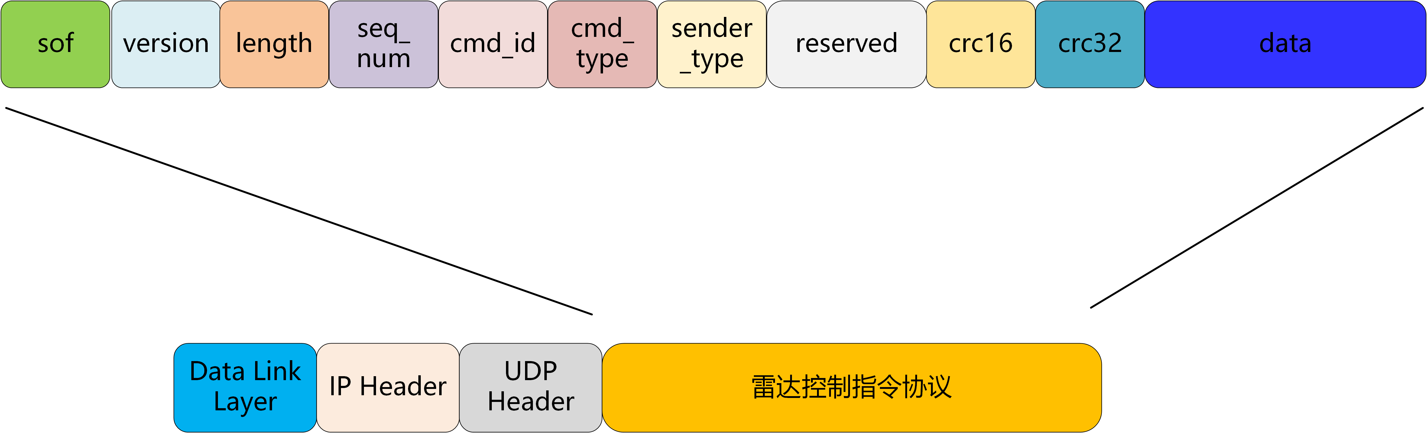
Format of control command is as follows:
Field |
Offset(byte) |
Size (byte) |
Description |
|---|---|---|---|
sof |
0 |
1 |
Starting byte, fixed to be 0xAA |
version |
1 |
1 |
Protocol version, 0 for current version |
length |
2 |
2 |
Length of frame; |
seq_num |
4 |
4 |
This field is incremented by 1 for each new REQ request message; |
cmd_id |
8 |
2 |
Different types of messages are distinguished by this field, For details, see (Command ID) |
cmd_type |
10 |
1 |
Command Type: |
sender_type |
11 |
1 |
The sender’s device type: 0 means the host computer sends the message, 1 means the LiDAR sends the message |
resv |
12 |
6 |
Reserved extension field, can be ignored |
crc_16 |
18 |
2 |
Frame header checksum, check data is 18 bytes from |
crc32 |
20 |
4 |
crc32 checksum: data field checksum, using CRC-32 algorithm (see (CRC Algorithm) for details) |
data |
24 |
n |
See (CMD Details) |
1.3.1.4.2. Command ID
LiDAR command id list:
Function Type |
CMD ID |
Function |
|---|---|---|
Device Type Query |
0x0000 |
Discovery by broadcasting |
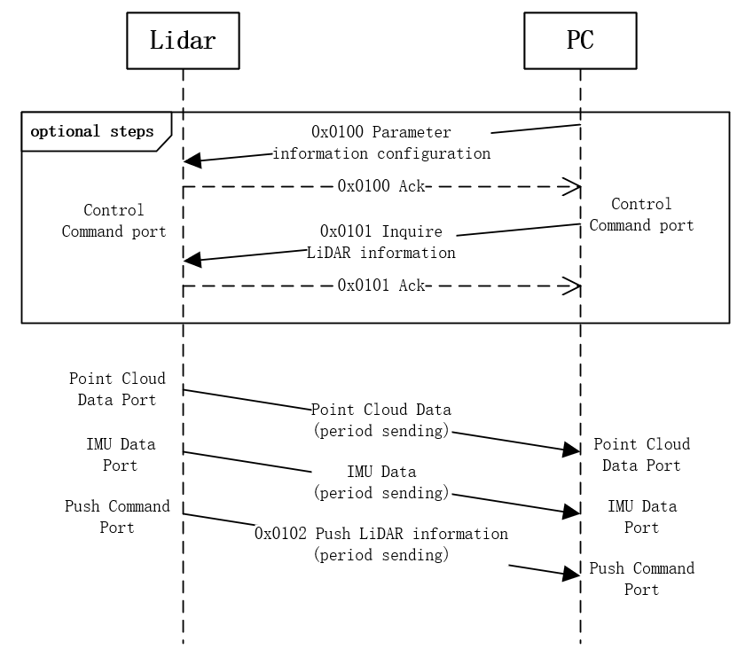
LiDAR Information |
0x0100 |
Parameter information configuration |
0x0101 |
Inquire LiDAR information |
|
0x0102 |
Push LiDAR information |
|
Control CMD |
0x0200 |
Request reboot device |
0x0201 |
Restore factory settings |
|
0x0202 |
Set GPS timestamp |
|
log CMD |
0x0300 |
Log file push |
0x0301 |
Log collection configuration |
|
0x0302 |
Log system time synchronization |
|
0x0303 |
Debug raw data collection configuration |
|
General Upgrade |
0x0400 |
Request to start upgrade |
0x0401 |
Firmware data transfer |
|
0x0402 |
Firmware transfer complete |
|
0x0403 |
Get firmware upgrade status |
1.3.1.4.3. Communication Process
1.3.1.5. CMD Details
1.3.1.5.1. Device Type Query
1.3.1.5.1.1. 0x0000 Discovery By Broadcasting
Request
CMD |
Name |
Offset(byte) |
Data Type |
Description |
|---|---|---|---|---|
data |
NULL |
ACK
ACK |
Name |
Offset(byte) |
Data Type |
Description |
|---|---|---|---|---|
data |
ret_code |
0 |
uint8_t |
Return code: |
dev_type |
1 |
uint8_t |
LiDAR type |
|
serial_number |
2 |
uint8_t[16] |
LiDAR SN |
|
lidar_ip |
18 |
uint8_t[4] |
LiDAR IP address |
|
cmd_port |
22 |
uint16_t |
Current control command port of the LiDAR |
1.3.1.5.2. LiDAR Information
1.3.1.5.2.1. 0x0100 Parameter Configuration
Request
CMD |
Name |
Offset(byte) |
Data Type |
Description |
|---|---|---|---|---|
data |
key_num |
0 |
uint16_t |
Number of |
rsvd |
2 |
uint16_t |
||
key_value_list |
4 |
key_value_list[N] |
Key content list; |
Format of each parameter in key_value_list is as follows:
Data Field |
Offset(byte) |
Data Type |
Description |
|---|---|---|---|
key |
0 |
uint16_t |
Key number, see the key table below |
length |
2 |
uint16_t |
Length of value to the key |
value |
4 |
– |
Value content to the key |
ACK
ACK |
Name |
Offset(byte) |
Data Type |
Description |
|---|---|---|---|---|
data |
ret_code |
0 |
uint8_t |
Return code: |
error_key |
1 |
uint16_t |
The first LiDAR key that failed to be configured |
1.3.1.5.2.2. 0x0101 Parameter Inquire
Request
CMD |
Name |
Offset(byte) |
Data Type |
Description |
|---|---|---|---|---|
data |
key_num |
0 |
uint16_t |
Number of entries in |
rsvd |
2 |
uint16_t |
||
key_list |
4 |
– |
Key number list |
The key type in the key_list:
Data Field |
Offset(byte) |
Data Type |
Description |
|---|---|---|---|
key |
0 |
uint16_t |
key number |
ACK
ACK |
Name |
Offset(byte) |
Data Type |
Description |
|---|---|---|---|---|
data |
ret_code |
0 |
uint8_t |
Return code: |
key_num |
1 |
uint16_t |
Number of |
|
key_value_list |
3 |
– |
Information of keys queried successfully |
1.3.1.5.2.3. 0x0102 LiDAR Information Push
LiDAR pushes actively
CMD |
Name |
Offset(byte) |
Data Type |
Description |
|---|---|---|---|---|
data |
key_num |
0 |
uint16_t |
Number of |
rsvd |
2 |
uint16_t |
||
key_value_list |
4 |
– |
info_list |
Format of each parameter in key_value_list is as follows:
Data Field |
Offset(byte) |
Data Type |
Description |
|---|---|---|---|
key |
0 |
uint16_t |
Key number, see the key table below |
length |
2 |
uint16_t |
Length of value to the key |
value |
4 |
– |
Content of pushed key information |
Specific meanings of key_value_list are as follows:
Number(key) |
Name |
Length |
Type |
Content |
Support Parameter Information Configuration Command(cmd_id=0x0100) |
|---|---|---|---|---|---|
0x0000 |
pcl_data_type |
1 |
uint8_t |
Type of point cloud data, see (Data Types): |
Yes |
0x0004 |
lidar_ipcfg |
12 |
uint8_t[12] |
LiDAR IP address configuration |
Yes |
0x0005 |
state_info_host_ipcfg |
8 |
uint8_t[8] |
IP address configuration for pushing LiDAR status information |
Yes |
0x0006 |
pointcloud_host_ipcfg |
8 |
uint8_t[8] |
IP address configuration for pushing LiDAR point cloud data |
Yes |
0x0007 |
imu_host_ipcfg |
8 |
uint8_t[8] |
IP address configuration for pushing LiDAR IMU data |
Yes |
0x001A |
work_tgt_mode |
1 |
uint8_t |
LiDAR target working mode (i.e. target working status), see (LiDAR Working Status) |
Yes |
0x001C |
imu_data_en |
1 |
uint8_t |
0: IMU data push disabled |
Yes |
0x0022 |
fov_mode |
1 |
uint8_t |
0: Focus Detection Mode |
Yes |
0x0024 |
echo_mode |
1 |
uint8_t |
0: Sorted by echo intensity, single-echo output returns the strongest echo |
Yes |
0x0025 |
NTP_server_ip |
4 |
uint8_t[4] |
IP address of the NTP server |
Yes |
0x0027 |
ITO_ctrl |
1 |
uint8_t |
Window glass heating enable: |
Yes |
0x0028 |
fog_noise_filter |
1 |
uint8_t |
Rain and fog noise filter enable: |
Yes |
0x8000 |
sn |
16 |
uint8_t[16] |
String type (Use ‘\0’ padding for less than 16 bits) |
No |
0x8002 |
version_app |
4 |
uint8_t[4] |
App firmware version number: aa.bb.cc.dd |
No |
0x8003 |
version_loader |
4 |
uint8_t[4] |
Loader firmware version number |
No |
0x8006 |
cur_work_state |
1 |
uint8_t |
Current working state of LiDAR |
No |
0x8007 |
core_temp |
4 |
int32_t |
Core temperature (Unit: 0.01℃) |
No |
0x8010 |
FW_TYPE |
1 |
uint8_t |
Firmware type: |
No |
0x0811 |
hms_code |
32 |
uint32_t[8] |
Diagnostic Trouble Code. Each non-0 value represents a piece of diagnostic information. When the LiDAR does not work normally, the cause of the problem can be confirmed through this diagnostic code |
No |
1.3.1.5.3. Control Command
1.3.1.5.3.1. 0x0200 Reboot Device
Request
CMD |
Name |
Offset(byte) |
Data Type |
Description |
|---|---|---|---|---|
data |
timeout |
0 |
uint16_t |
Reboot device delay time: ms |
ACK
ACK |
Name |
Offset(byte) |
Data Type |
Description |
|---|---|---|---|---|
data |
ret_code |
0 |
uint8_t |
Return code: |
1.3.1.5.3.2. 0x0201 Restore Factory Settings
After this command is issued, the LiDAR will be restored to the factory settings. After the reply is successful, the LiDAR will reboot immediately to take effect.
Request
CMD |
Name |
Offset(byte) |
Data Type |
Description |
|---|---|---|---|---|
data |
SN |
0 |
uint8_t[16] |
Reserved |
ACK
ACK |
Name |
Offset(byte) |
Data Type |
Description |
|---|---|---|---|---|
data |
ret_code |
0 |
uint8_t |
Return code: |
1.3.1.5.3.3. 0x0202 Set GPS Timestamp
Request
CMD |
Name |
Offset(byte) |
Data Type |
Description |
|---|---|---|---|---|
data |
type |
0 |
uint8_t |
Time synchronization method: |
time_set |
1 |
uint64_t |
If GPS synchronized, this field should be the time of the last rising edge of the PPS signal, the type is uint64_t, unit: ns |
ACK
ACK |
Name |
Offset(byte) |
Data Type |
Description |
|---|---|---|---|---|
data |
ret_code |
0 |
uint8_t |
Return code: |
1.3.1.5.4. Log Command
1.3.1.5.4.1. 0x0300 Log file push
Requester: LiDAR
CMD |
Name |
Offset(byte) |
Data Type |
Description |
|---|---|---|---|---|
data |
log_type |
0 |
uint8_t |
Log type: |
file_index |
1 |
uint8_t |
File index |
|
file_num |
2 |
uint8_t |
This field is valid only when log_type is flash log, it means the number of flash log files |
|
flag |
3 |
uint8_t |
bit 0: |
|
timestamp |
4 |
uint32_t |
unix timestamp, this count starts at the Unix Epoch on January 1st, 1970 at UTC. |
|
rsvd |
8 |
uint16_t |
||
trans_index |
10 |
uint32_t |
Send index |
|
log_data_len |
14 |
uint16_t |
Log content length |
|
log_data |
16 |
– |
Log content: |
Responder: Host computer
ACK |
Name |
Offset(byte) |
Data Type |
Description |
|---|---|---|---|---|
data |
ret_code |
0 |
uint8_t |
Return code: |
log_type |
1 |
uint8_t |
||
file_index |
2 |
uint8_t |
||
trans_index |
3 |
uint32_t |
1.3.1.5.4.2. 0x0301 Log collection configuration
Requester: Host computer
CMD |
Name |
Offset(byte) |
Data Type |
Description |
|---|---|---|---|---|
data |
log_type |
0 |
uint8_t |
Log type: |
enable |
1 |
uint8_t |
0 : disable |
Responder: LiDAR
ACK |
Name |
Offset(byte) |
Data Type |
Description |
|---|---|---|---|---|
data |
ret_code |
0 |
uint8_t |
Return code: |
1.3.1.5.4.3. 0x0302 Log system time synchronization
Requester: Host computer
CMD |
Name |
Offset(byte) |
Data Type |
Description |
|---|---|---|---|---|
data |
timestamp |
0 |
uint32_t |
unix timestamp, this count starts at the Unix Epoch on January 1st, 1970 at UTC |
Responder: LiDAR
ACK |
Name |
Offset(byte) |
Data Type |
Description |
|---|---|---|---|---|
data |
ret_code |
0 |
uint8_t |
Return code: |
1.3.1.5.4.4. 0x0303 Debug raw data collection configuration
Requester: Host computer
CMD |
Name |
Offset(byte) |
Data Type |
Description |
|---|---|---|---|---|
data |
enable |
0 |
uint8_t |
0: disable |
host_ip |
1 |
uint8_t[4] |
Debug raw data destination IP address: AA.BB.CC.DD |
|
host_port |
5 |
uint16_t |
Debug raw data destination port |
|
reserved |
7 |
uint16_t |
Reserved |
Responder: LiDAR
ACK |
Name |
Offset(byte) |
Data Type |
Description |
|---|---|---|---|---|
data |
ret_code |
0 |
uint8_t |
Return code: |
1.3.1.5.5. General Upgrade
1.3.1.5.5.1. 0x0400 Request to Start Upgrade
Request
CMD |
Name |
Offset(byte) |
Data Type |
Description |
|---|---|---|---|---|
data |
firmware_type |
0 |
uint8_t |
Firmware type: |
encrypt_type |
1 |
uint8_t |
Firmware encryption type: |
|
firmware_length |
2 |
uint32_t |
Total firmware length |
|
dev_type |
6 |
uint8_t |
Device type: |
ACK
ACK |
Name |
Offset(byte) |
Data Type |
Description |
|---|---|---|---|---|
data |
ret_code |
0 |
uint8_t |
Return code: |
1.3.1.5.5.2. 0x0401 Firmware Data Transmit
Request
CMD |
Name |
Offset(byte) |
Data Type |
Description |
|---|---|---|---|---|
data |
firmware_offset |
0 |
uint32_t |
|
current_length |
4 |
uint32_t |
||
encrypt_type |
8 |
uint8_t |
||
rsvd |
9 |
uint8_t[3] |
||
data |
12 |
uint8_t[n] |
Firmware data |
ACK
ACK |
Name |
Offset(byte) |
Data Type |
Description |
|---|---|---|---|---|
data |
ret_code |
0 |
uint8_t |
Return code: |
current_offset |
1 |
uint32_t |
||
received_length |
5 |
uint32_t |
1.3.1.5.5.3. 0x0402 Firmware Transmit Complete
Request
CMD |
Name |
Offset(byte) |
Data Type |
Description |
|---|---|---|---|---|
data |
checksum_type |
0 |
uint8_t |
|
checksum_length |
1 |
uint8_t |
||
checksum_data |
2 |
uint8_t[n] |
ACK
ACK |
Name |
Offset(byte) |
Data Type |
Description |
|---|---|---|---|---|
data |
ret_code |
0 |
uint8_t |
Return code: |
1.3.1.5.5.4. 0x0403 Get Firmware Upgrade State
Request
CMD |
Name |
Offset(byte) |
Data Type |
Description |
|---|---|---|---|---|
data |
NULL |
|||
ACK
ACK |
Name |
Offset(byte) |
Data Type |
Description |
|---|---|---|---|---|
data |
ret_code |
0 |
uint8_t |
Return code: |
upgrade_progress |
1 |
uint8_t |
Upgrade progress: |
1.3.1.6. Return Code Description
Name |
Return Code |
Description |
|---|---|---|
LVX_RET_SUCCESS |
0x00 |
Execution succeed |
LVX_RET_FAILURE |
0x01 |
Execution failed |
LVX_RET_NOT_PERMIT_NOW |
0x02 |
Current state does not support |
LVX_RET_OUT_OF_RANGE |
0x03 |
Setting value out of range |
LVX_RET_PARAM_NOTSUPPORT |
0x20 |
The parameter is not supported |
LVX_RET_PARAM_REBOOT_EFFECT |
0x21 |
Parameters need to reboot to take effect |
LVX_RET_PARAM_RD_ONLY |
0x22 |
The parameter is read-only and cannot be written |
LVX_RET_PARAM_INVALID_LEN |
0x23 |
The request parameter length is wrong, or the ack packet exceeds the maximum length |
LVX_RET_PARAM_KEY_NUM_ERR |
0x24 |
Parameter |
LVX_RET_UPGRADE_PUB_KEY_ERROR |
0x30 |
Public key signature verification error |
LVX_RET_UPGRADE_DIGEST_ERROR |
0x31 |
Firmware digest signature verification error |
LVX_RET_UPGRADE_FW_TYPE_ERROR |
0x32 |
Firmware type mismatch |
LVX_RET_UPGRADE_FW_OUT_OF_RANGE |
0x33 |
Firmware length out of range |
LVX_RET_UPGRADE_FW_ERASING |
0x34 |
Firmware erasing |
1.3.1.7. CRC Algorithm
CRC Name |
Polynomial Formula |
Width |
Polynomial |
Initial Value |
Result XOR value |
Input Reverse |
Output Reverse |
|---|---|---|---|---|---|---|---|
CRC-16/CCITT-FALSE |
x^16^ + x^12^ + x^5^ + 1 |
16 |
0x1021 |
0xFFFF |
0x0000 |
false |
false |
CRC-32 |
x^32^ + x^26^ + x^23^ + x^22^ + x^16^ + x^12^ + x^11^ + x^10^ + x^8^ + x^7^ + x^5^ + x^4^ + x^2^ + x + 1 |
32 |
0x04C11DB7 |
0xFFFFFFFF |
0xFFFFFFFF |
true |
true |